Circuit construction
For almost all features of reef-pi that can be used to do anything on a reef tank, we’ll need additional electronic component other than just Raspberry Pi. This guide will walk through some key aspects and recommendations of wiring different electronic component together to build a functional reef-pi controller. Users who are well versed in electronics can skip this
Factors that influence circuit work
Controller features
reef-pi can automate a host of different reef keeping chores, and each of them may require one or more electronic component just for that feature. Hence, more features will lead more component thus making wiring effort much harder. A simple power controller which can control two electrical equipment can be as trivial as only connecting four wires with one additional board. While a Kessil LED controller may involve eight different wiring, an additional board, an additional power supply and up to 6 other component. It may sound daunting for the beginners, but since reef-pi is modular, one can build their controller iteratively thus wiring only some parts at a time. This is particularly workable since one can sync their controller build as their reef tank matures (e.g. build dosing controller when tank matures enough to keep sps). For the avid DIY hackers, this means they can opt for custom electronic component (like using a modular power source hidden inside the controller instead of wall warts).
Builder’s skill level
It is of utmost importance that we keep our livestock, tank & users safe. Since this is DIY build, there is lot more source of errors and associated risks. Please consider choosing electronics that match your skill level. If you are a beginner, go with the recommended list and test your controller before you put it on active duty. If users are new to electronics go for a breadboard and some jumper wires to test your reef-pi build, before you put your controller in active duty, where it is likely to be a permanent installation and the wiring may involve soldering instead of breadboards.
Multi unit or a single All in one housing
Permanent installations of reef-pi should always be secured physically. Which means building a housing for the controller, exposing all input (like sensors) and outputs (like electrical socket, dc jacks) via connectors that are physically secured on the housing (e.g. panel mounted barrel jacks or audio jacks). For builds involving electrical (i.e. 110v or 220v AC) equipment use protective circuits such as fuse, surge protectors and GFCI. These can be internal (present inside the housing) or external (i.e. reef-pi controller is connected to a GFCI outlet). It is common best practice to separate the electrical circuits from rest of the controller, i.e. power bars and relay board is physically separate. How the overall controller is designed, whether it is split across multiple units (the core controller being one, and different modules, such as dosing system being separate units) or everything is combined into one big all-in-one style unit, will also greatly influence the complexity of the circuit involved.
Recommendations
Connectors & Headers
For some component, such as Kessil Lights, the type of connectors depends upon the equipment. For others, we get to choose them. Following is the recommmended set of connectors:
- 3.5 mm audiojacks: For temperature probes.
- barrel jacks: For power heads or independent LED channels where relatively high power source is controlled.
- BNC jacks: For ph and other probes.
- Pin headers: For wiring different component with the housing, that are not connectors.
- JST connectors: For wiring different component within housing with connectors. These are optional, normal pin headers can be used as well, but recommended for permanent installations.
Boards
Typical reef-pi builds will involve building circuits on top of an electronic board. Consider at least one or multiple of these type of boards.
- Breadboard: If you are new to electronics, I highly recommend getting a breadboard first and test out your component and reef-pi together on a breadboard. Remember, this is not a suitable method for a permanent installation. It may work out for a really simple circuit, for few months. But for typical reef tanks that last for years, this is sub optimal
- Perma proto board: Perma protoboards are easy to solder boards with better physical form factor, and can be found as exactly same shape of Raspberry Pi. Making them a perfect fit for stacking on top of your raspberry pi. Make sure you work out all the circuit details before soldering or leave ample of extra space. If you plan to build reef-pi controller iteratively, go with perma protoboard but don’t stack them this will allow easy distribution of future electronic component horizontally.
Power source
Various component of a reef-pi build may require different types of electrical power. At a minimum, we need a 5 volt DC power supply for Raspberry Pi, while in some cases we may need multiple different DC voltage source, such as 5 volt for Pi, 3.3 volt for probes, 10 volt for LED control, 12 volt dosing pump, 24 volts power heads etc. There are couple of ways to go about this,
Wall wart power source: This is the simplest, fairly safe route. Where each power requirement has its own power source using a wall wart adapter. These are available in various strength, can ve sourced easily. They are also safer due to physical isolation. They are are challenging due to the higher number of connectors and external wires involved in them. For beginners we always recommend going with wall warts. reef-pi recommended Bill of Materials contains a 5 volt, 2.5 A wall wart for powering raspberry pi, and 12 volt 1 A wall wart for powering kessil or any other 12v component.
PCB modules: There are dedicated PCB modules that can be embedded inside the controller to power different electronic component. These are relatively harder to source, involves more soldering and incur more space inside the housing, but makes the entire controller look more elegant by reducing number of wall warts. If chosen carefully (appropriate current, voltage, manufacturer) they can easily out-compete wall warts. reef-pi recommended Bill of Materials contains a PCB module to provide a 12 volt 1A and a 5 volt 1 A dc power straight from AC source.
Voltage regulators: These component stabilize a power source to a fixed voltage. These are popular component to ensure optimal performance to sensitive electronics and ensure their longevity. Depending upon the power source, they can be a must or good to have component in reef-pi build. reef-pi builds involving unregulated power supplies must use voltage regulators for permanent installation. Voltage regulators can be fixed, providing a steady fixed voltage power source (such as lm7805 which gives steady 5 volt DC power) or adjustable (such as lm2596) that can be configured to provide stead voltage across a range. reef-pi recommended Bill of materials contains an adjustable voltage regulator. Throughout our build guides, we’ll use LM2596 modules for different power sources.
Power mosfets or high power darlingtons: It is possible to control almost any DC equipment using reef pi, even if they don’t support it out of the box. Example of these will relatively cheaper LED bulbs (Par38). For such cases users can almost always control the device’s power source directly using a logic level power mosfet. This technique can be used to power custom DC power heads or fans. This is somewhat custom and reef-pi does not have any specific documentation, since it varies with individual cases, but the recommended Bill of Material contains an N channel power mosfet to support such cases.
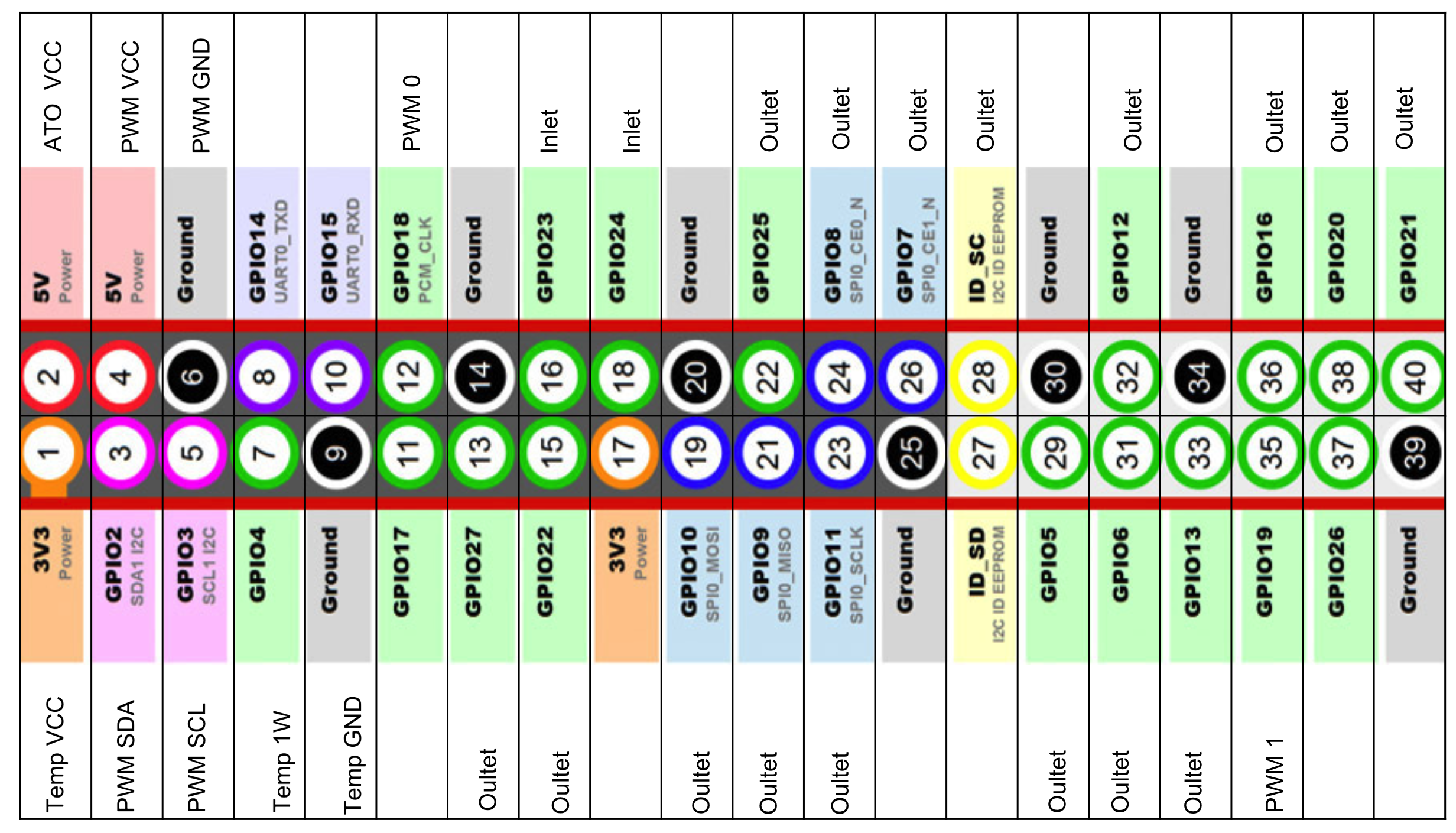
Raspberry Pi pin layout
While configuring reef-pi, users have to specify pin number in different places (e.g. jacks, ato). Always specify GPIO pin number, not the serial number (that reflects their physical positions), this is a common mistake. For example GPIO pin 17 is commonly denoted as pin 11 (based on its location), so when using that pin as outlet or inlet in reef-pi, always specify 17 as the pin number, not 11. Some pins are reserved for specific purposes and can not be used for anything else. We offer a recommended pin out list to ease this process. In the recommended pin out, all relay pins are grouped together to simplify wiring. In some cases (such as ATO and temperature controller) they are also the default values in reef-pi software, which reduces the chance of mistakes. The Raspberry Pi hardware PWMs are exposed via GPIO 18 and 19, in reef-pi configuration they are represented as jacks with rpi driver and pin number 0 (for GPIO 18) and pin number 1 (for GPIO 19).